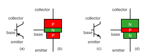
Transistors are created by either stacking an n on top of a p on top of an n, or p over n over p. The schematic symbol for a pnp transistor can always be distinguished from an npn transistor as the A. A bipolar junction transistor ( BJT) is a type of transistor that uses both electrons and electron holes as charge carriers. A semiconductor material with extra electrons is called an n-type ( n for negative because electrons have a negative charge) and a material with electrons removed is called a p-type (for positive).

Some of those layers have extra electrons added to them (a process called "doping"), and others have electrons removed (doped with "holes" - the absence of electrons). The topics discussed in these slide is PNP Transistor Symbol Of Electrical Circuit. Transistors are built by stacking three different layers of semiconductor material together. Presenting this set of slides with name PNP Transistor Symbol Of Electrical Circuit. This transistor mainly consists of 3 terminals and they are Emitter (E), Collector (C) and Base (B). Using the diode (or resistance) test function on a multimeter, you can measure across the BE and BC terminals to check for the presence of those "diodes".) Transistor Structure and Operation Table of transistor symbols pnp transistor symbol, PNP Bipolar Transistor, Allows current flow when low potential at base (middle) darlington transistor. The above figure shows the structure and symbol of PNP Transistor. (This model is useful if you need to test a transistor. Darlington transistor symbol: The Darlington transistor symbol consists of two NPN transistors connected in series, with a circle representing the common collector and two rectangles representing the bases of the transistors. There's a whole lot of weird quantum physics level stuff controlling the interactions between the three terminals. The PNP transistor symbol is similar to that of an NPN transistor, but with the arrow pointing in the opposite direction. Don't base your understanding of a transistor's operation on that model (and definitely don't try to replicate it on a breadboard, it won't work). Draw the symbol of enhancement and depletion N channel MOSFET. The diode representation is a good place to start, but it's far from accurate. Draw the symbol of NPN and PNP transistor. The diode connecting base to emitter is the important one here it matches the direction of the arrow on the schematic symbol, and shows you which way current is intended to flow through the transistor.


 0 kommentar(er)
